How to Design an Off-Grid Power System – A Step-by-Step Primer
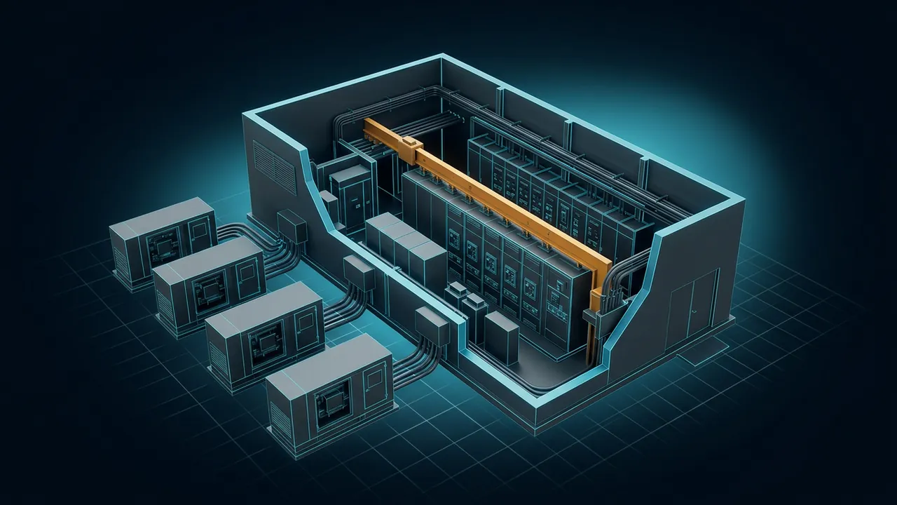
On the grid, a power system designer gets a quiet gift: an infinite bus. Somewhere out there, thousands of megawatts of spinning machines hold the frequency steady no matter what your site does. Take that away and every decision changes, which is the first lesson in how to design an off-grid power system. Your largest motor start, your biggest generator trip and your fuel supply now belong to you alone. How do you design an off-grid power system that stays up?
To design an off-grid power system, you work through the same steps every time: define the load, set a reliability target, choose the generation technology and unit size, add redundancy, secure the fuel, add storage for load steps and black start, design controls and protection, then test everything under real conditions.
The order matters, because each step depends on the one before. Load and reliability drive the number and size of generators; the generators drive fuel and storage needs; and the controls tie it all together. Designs that skip the load-step and fault cases look fine on paper and trip on their first bad day.
Step 1: Define the Load, Not Just the Peak
Start with how the load behaves, not only how big it is. You need four numbers:
- Average load: drives fuel use and how hard the units work.
- Peak load: drives installed capacity.
- Largest load step: the biggest chunk that can switch on or off at once, such as a large chiller start or a block of equipment transferring.
- Growth: what the site will need in five or ten years.
For a data center, a common shortcut is IT load times power usage effectiveness (PUE). Our running example: 20 megawatts (MW) of IT load at a design PUE of 1.3 gives 20 × 1.3 = 26 MW of facility load. For an oil field, mine or remote camp, build the list from motors, heaters and process loads instead, and pay special attention to large motor starts, which can draw several times their running current for a few seconds.
Step 2: Set a Reliability Target and Redundancy
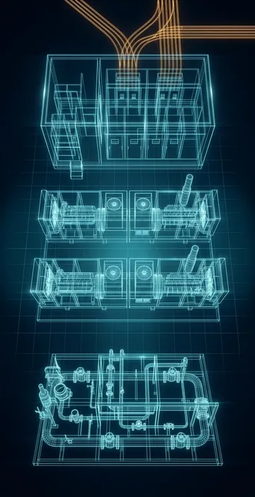
Decide how much downtime the load can tolerate, then turn that into spare capacity. The core rule for an island is simple: the plant must survive the loss of its largest running unit without dropping critical load. That is N+1. Because units also go down for planned maintenance, most critical off-grid plants use N+2: one unit out for service, one more ready to trip.
Why not trust a single big machine? Because no generator is available 100% of the time. If each unit is available roughly 97% of the time, a plant with zero spares will be short of capacity for a meaningful number of hours every year. Each spare unit cuts that dramatically.
A Quick Availability Check
Here is the arithmetic behind that claim, as a simple model. Suppose the site needs 11 units running and each unit is independently available 97% of the time.
- With exactly 11 installed, all 11 must be up: 0.9711 ≈ 0.715. The plant is short of capacity about 28.5% of the time, roughly 2,500 hours a year.
- With 12 installed (N+1), the plant is short only when two or more units are down at once. That works out to about 4.9% of the time, roughly 430 hours a year.
- With 13 installed (N+2), it falls to about 0.6%, roughly 55 hours a year, and some of that can be covered by load shedding or batteries.
The model is crude, since real outages are not perfectly independent and planned maintenance can be scheduled, but it shows why two spares are normal for an island.
Step 3: Choose the Generation Technology
Most off-grid plants above a few megawatts use natural gas reciprocating engines, gas turbines, or a mix, often with batteries and sometimes solar. The table compares the usual options.
| Option | Strengths off-grid | Watch-outs |
|---|---|---|
| Gas reciprocating engines | Good efficiency at part load, better load-step response than most turbines (though not diesel), modular unit sizes | More units to maintain, more moving parts |
| Gas turbines | High power density, fewer units, low maintenance per MW | Weaker at large block loads, efficiency drops at part load and in hot weather |
| Diesel engines | Simple fuel storage, strong load acceptance | Fuel cost and logistics, emissions limits for prime duty |
| Solar plus batteries | No fuel cost during the day | Needs firm backup for nights and cloudy stretches |
Pick the right rating, too. Standby ratings are for emergency use and limited hours. An off-grid plant runs all year, so it needs prime or continuous ratings. In Cummins' summary of ISO 8528 generator set ratings, emergency standby assumes about 200 hours a year at a 70% average load, prime allows unlimited hours at a 70% average load, and continuous allows unlimited hours at 100% load.
Step 4: Size the Units
Unit size is a trade between economy and resilience. Bigger units mean fewer machines and lower cost per kilowatt. Smaller units mean each trip is a smaller hit, and each spare costs less.
Worked example for our 26 MW site, using 2.5 MW gas engines:
- Units needed to carry the load: 26 ÷ 2.5 = 10.4, rounded up to 11 running units.
- Add N+2 redundancy: 11 + 2 = 13 installed units.
- Installed capacity: 13 × 2.5 = 32.5 MW.
- Loss of one running unit drops 2.5 MW, under 10% of the load, which batteries and the remaining engines can absorb.
Real projects also derate for altitude and ambient temperature and keep units below full load so they have headroom for load steps. You can try your own numbers with the calculator below.
If your load is a data center, our guide on how many generators a data center has covers fleet sizing in more detail.
Step 5: Secure the Fuel
An off-grid plant is only as reliable as its fuel. For gas, calculate daily burn at full load, then make sure the supply can deliver it every day of the year.
Worked example, continuing with 26 MW and an assumed heat rate of 8,500 British thermal units per kilowatt-hour (Btu/kWh):
- Daily energy: 26,000 kW × 24 hours = 624,000 kWh.
- Fuel energy: 624,000 × 8,500 = 5.3 billion Btu, or about 5,300 million Btu (MMBtu) per day.
- Gas volume at 1,036 Btu per cubic foot: 5,304,000,000 ÷ 1,036 ≈ 5.1 million cubic feet per day (MMcf/d).
Then ask the hard questions. Is the pipeline supply firm or interruptible? Is gas quality steady, or does it need conditioning? Is there a backup, such as dual-fuel engines with stored diesel, or compressed or liquefied natural gas delivered by truck? A plant with one fuel path has one big single point of failure.
Step 6: Add Storage for Load Steps and Black Start
Batteries do jobs that engines cannot do fast enough. They catch the load in the first fraction of a second after a unit trips, soften large load steps, and let engines run at steadier output.
A simple sizing approach: make the battery's power rating at least as large as the largest running unit, and give it enough energy to carry that power while a standby engine starts and loads. For our example, 2.5 MW for 15 minutes is 2.5 × 0.25 = 0.625 megawatt-hours (MWh). Designers often add margin for battery aging and for multiple events.
Plan black start too. If the whole plant goes dark, something must start the first engine and energize the bus. That can be the battery system with a grid-forming inverter, a small diesel generator, or engines with their own battery starters. Write down the black start sequence and test it.
Step 7: Design Controls and Protection
Controls are what turn a pile of generators into a power plant. On an island, one control scheme must hold frequency and voltage while sharing load among units. Common approaches use isochronous load sharing, where units together hold exact frequency, or droop control with a supervisory controller trimming it back. A plant or microgrid controller decides how many units run, when to start a spare, and when to shed load.
Load shedding is the safety net. Rank loads into tiers, from must-never-drop to can-wait, and set under-frequency relays or controller logic to drop the lowest tiers first if the plant runs short.
Protection is harder than on the grid. Generators supply much less fault current than a utility, and inverter-based batteries and solar supply even less. Relays must still detect and clear faults quickly, so the protection study should model the weakest realistic case, such as the fewest units online at night.
Step 8: Lay Out the Electrical System
Most multi-megawatt off-grid plants connect generators to a medium-voltage paralleling bus, often split into two halves with a tie breaker. If one bus section faults, the other keeps running. Feeders then carry power to the load buildings, where transformers step it down. Keep the one-line diagram simple enough that operators understand it in the middle of the night.
Give grounding its own attention. With no utility source, the system ground comes from the generators and transformers on site, so the grounding method (solidly grounded, low-resistance or high-resistance) must keep working correctly whether two units are online or twelve. Ground faults that go undetected on an island tend to become bigger faults later.
Step 9: Plan Permits, Maintenance and People
Engines and turbines that run all year need air permits, and the limits can affect technology choice and unit count. Maintenance is constant: oil changes, inspections and overhauls on a schedule set by running hours. Build that into your redundancy, since a unit in overhaul is not a spare. And plan for trained operators, on site or remote, around the clock, plus a stock of critical spare parts, because the nearest replacement starter or control card may be days away.
Step 10: Test Before You Trust It
Test each generator at the factory, then test the full plant on site. The commissioning list should include load bank runs at stepped loads, real load step tests, a forced trip of the largest running unit, load shedding operation and a full black start from dark. Every test that fails during commissioning is one that did not fail in production.
How to Design an Off-Grid Power System That Survives Its Worst Day
The steps for how to design an off-grid power system are the same whatever the load: know the load, decide what failures it must survive, size and multiply the units, secure the fuel, add storage, control and protect it, then test it hard. In our example, 26 MW of load turned into 13 gas engines, about 5.1 MMcf/d of gas and a battery sized to catch the loss of one unit.
Your next step is to write down the worst day your site could face, whether a unit trip, a fuel interruption or a big load step, and check that every part of the design has an answer for it. Then bring in experienced engineers to turn the sketch into a real design.